


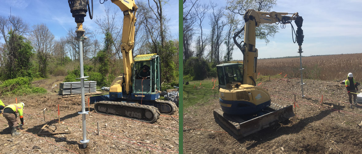
The driving force behind most walkway, boardwalk, and pedestrian bridge foundations is environmental sensitivity – with difficult access, mobilization limits, and layered regulatory oversight close behind. Danbro’s walkway experience runs nearly three decades across a coastal, wetland-heavy territory, and no distributor has supported more of these projects. The Fort Delaware State Park Walkway is the case that compresses every one of those constraints into a single site.
Fort Delaware sits on Pea Patch Island in the middle of the Delaware River. The park was adding an elevated walkway and a raised pavilion to one of its pedestrian trails, with the new lookout positioned directly across from a rookery for herons, egrets, and other waterfowl – birdwatching is a primary draw for the site. The foundation had to carry an elevated structure in a marine flood zone, inside a protected habitat, on an island with no road or bridge access.
Site Constraints That Drove the Design
Four conditions shaped the foundation system before a single pile was selected:
- Ferry-only access. Every pile, extension, bracket, and piece of installation equipment was transferred to the island by ferry. There is no barge landing for a crane, no road for a concrete truck, and no staging yard.
- A hard daily clock. The installation crew was boated out in the morning and returned at 4:00 PM. Every production day was capped by the ferry schedule, not by the work.
- Spring weather on open water. The tight spring schedule met frequent inclement weather in the middle of a river – uncomfortable working conditions and recurring construction delays, per the project record.
- Habitat sensitivity. With an active rookery adjacent to the work and the site tagged for marine, coastal, flood-zone, and environmental sensitivity, excavation, spoils, and heavy-equipment ground disturbance were all unacceptable.
Driven piles require a crane and leads that cannot reach the site. Drilled or cast-in-place foundations require excavation, spoils handling, concrete delivery, and cure time, none of which a ferry schedule or a protected wetland will tolerate. Helical piles are the system engineered for this envelope: compact equipment, no excavation, no spoils, no cure period, and capacity verified during installation.
The Design: Two Pile Types, Two Load Paths
The foundation comprised 33 helical piles installed to a depth of 45 feet, split by function:
- 28 compression piles – IDEAL 3.5-inch pipe piles (3500.300, .300 wall) with 10-foot triple-helix leads and 10-foot extensions, supporting the walkway and observation deck gravity loads. Ultimate capacity: 23 kips per pile. Shaft torque rating: 17,000 ft-lb.
- 5 tension batter piles – IDEAL 1-1/2-inch square shaft with 7-foot triple-helix leads and 10-foot extensions, installed on a batter beneath the observation deck to resist lateral and uplift demands. Ultimate capacity: 2 kips tension per pile. Shaft torque rating: 7,000 ft-lb.
The material order tells the soil story the portfolio summary leaves out: the pipe piles were ordered at 60 feet of length to get through 45 feet of weight-of-hammer material – overburden so soft that a standard penetration test sampler advances under the weight of the hammer alone, with no blows counted. Danbro’s Pat Haffert describes the ground plainly: very soft and marshy, soft enough that at one point the installation machine bogged down in the muck and a second machine had to be brought in to drag it out. That is the river-island profile every selection below was made for.
The two-system approach is worth unpacking for engineers evaluating similar structures.
Round pipe shaft in compression. Over a 45-foot embedment through weight-of-hammer overburden that offers essentially no lateral support, a 3.5-inch pipe shaft provides the section modulus and bending stiffness to carry compression without buckling where lateral soil support is minimal. The same logic drove the pipe-shaft selection on the 304 Johnson Avenue underpinning in Jersey City – different structure, same soil mechanics.
Square shaft on a batter in tension. IDEAL’s square shaft piles are the manufacturer’s standard for tension and anchor applications, delivering the highest torque efficiency per pound of steel. A raised pavilion on open water sees wind loading that resolves into overturning and uplift at the foundation; installing the tension piles on a 45-degree batter converts that lateral demand into axial tension the helix plates are designed to resist. The angle is deliberate: at 45 degrees, each pile’s axial capacity divides evenly between horizontal restraint and vertical uplift resistance, so one anchor addresses both demands. ICC-ES AC358 establishes torque correlation for tension loading at embedment depths of 12 helix diameters or more below grade – 14 feet for the 14-inch plate on these leads. Even measured vertically, a 45-foot pile on a 45-degree batter reaches roughly 32 feet below grade, more than double the requirement.
Helix configuration. Both pile types ran triple-helix leads with 10-, 12-, and 14-inch plates – a 10-foot lead on the pipe piles and a 7-foot lead on the square shaft. The three-plate stack is the right call for this profile: with no bearing available in 45 feet of soft material, the pile needs maximum plate area once it reaches the competent stratum, and the ascending diameters let each plate cut its own path rather than disturbing the soil the plate above it will bear on. For specifiers, the principle holds: helix diameter and count are sized to the bearing stratum, not to the load alone, and the final installation torque is what confirms the selection worked.
Capacity Verification Without a Load Frame
On an island with a 4:00 PM ferry, the ability to verify capacity in minutes rather than days is not a convenience – it is the only practical QA/QC method available.
Helical capacity correlates to installation torque through the relationship Q<sub>u</sub> = K<sub>t</sub> × T, where K<sub>t</sub> is the capacity-to-torque ratio for the specific shaft and T is the final installation torque. K<sub>t</sub> is not a universal constant: it varies with shaft size and soil conditions, which is why the design professional selects the factor from the manufacturer’s evaluation report and design guidelines for the product in use. Recent full-scale load testing published through the Deep Foundations Institute has expanded the empirical basis for these factors across shaft diameters from 1.5 inches to 18 inches.
For Fort Delaware, the practical implication is direct: each of the 28 compression piles was advanced until the torque reading correlated to the 23-kip ultimate capacity at or below the 45-foot design depth, and each tension pile until it met the 2-kip tension requirement. The torque log became the capacity record for every pile before the crew boarded the afternoon ferry – and with required torque for a 23-kip ultimate well inside the pipe shaft’s 17,000 ft-lb rating, the shaft never became the limiting element. With the factor of safety of 2 typical for torque-monitored helical installations, those ultimate values translate to allowable working loads of roughly 11.5 kips in compression and 1 kip in tension – the engineer of record sets the final basis, but the installation produced the documentation to support it.
Load Transfer and Service Life
Walkway framing connects to the piles through purpose-built load transfer devices, and the Fort Delaware order shows the full set. The compression piles were capped with the IDEAL 3500 Boardwalk Bracket – a compression plate with a 6-inch saddle and 1/2-inch plates for outer gravity framing – alongside 8x8x3/4-inch double-bolt new-construction brackets and 5×5 angle brackets with plates where the walkway framing called for them.
The tension batter piles took a different connection entirely. Each square shaft terminated in a 1-1/2-inch adapter with a female thread receiving 1-inch 8-thread all-thread bar, run in 6-foot lengths with matching washers and nuts, to carry uplift from the observation deck framing down into the anchor. It is the same tie-down logic used on helical tiebacks: resolve the demand into axial tension and connect through a threaded assembly that can be tensioned and locked off.
In a marine flood zone, corrosion design is not optional, and every item on this order – piles, extensions, brackets, adapters, bar, washers, nuts – was supplied hot-dip galvanized. IDEAL’s standard protection for small-diameter piles is galvanizing, with sacrificial steel thickness designed into large-diameter products. Specifiers should state the design life and the soil and water chemistry so the protection method matches the exposure; on an island in the Delaware River, the answer was galvanize all of it.
Mobilization: Engineering the Logistics
The equipment on record was a Yanmar 87 E Pro compact excavator fitted with a hydraulic drive head – a machine that fits on a ferry. Thirty-three piles at a 45-foot installed depth – with the pipe piles ordered at 60 feet of material to reach it – represents well over 1,500 lineal feet of lead and extension, plus brackets, threaded bar, and tooling, every foot of it transferred by boat and sequenced against the daily cutoff.
The ground conditions that drove the pile design also drove the logistics. When the compact excavator got stuck in the marsh, the recovery machine could not simply be called in from the yard – it had to be scheduled onto a ferry. On a remote site, equipment recovery is a mobilization event, not a phone call, and it belongs in the plan before the first pile is loaded onto the boat.
This is the mobilization profile that makes helicals viable where nothing else is. On other Danbro walkway projects – Gunstock Mountain Resort in New Hampshire and the Appalachian Trail Walkway – access was restricted enough that all installation was completed with portable handheld equipment. Marine jobs such as the Sandy Bottom Pedestrian Bridges and the WMCA Catwalk Replacement were installed from barges with no land access at all. The equipment scales to the site; the engineering stays the same.
The Result
The elevated walkway and raised pavilion were delivered on their helical foundation with no excavation, no spoils removed from the island, and no disturbance to the rookery the structure was built to observe. Pea Patch Island has since hosted a second helical project – the Fort Delaware maintenance building, a separate 40-pile installation under the same ferry-only constraints.
Project team: Installing contractor: RE ECO Drill LLC. Engineer: CDA Engineering. General contractor: Merit Engineering and Construction.
Five Takeaways for Specifying Walkway Foundations
- Design the logistics before the piles. On remote sites, the access constraint determines the equipment, the equipment determines the pile series, and the daily production window determines the schedule. Start the design from the ferry, not from the load table – and if the ground is soft enough to need 45 feet of pile, it is soft enough to swallow the machine installing it. Plan the recovery.
- Separate the load paths. Gravity loads and lateral or uplift loads call for different shafts. Pipe shaft for compression stiffness over long unbraced lengths; square shaft on a batter for tension efficiency. Specify both, with their own capacity and torque criteria.
- Verify embedment for tension correlation. AC358’s torque correlation for tension applies at 12 helix diameters of embedment or more. Confirm the criterion is met before relying on torque as the tension capacity record.
- Treat torque correlation as the QA/QC program. On sites where load-frame testing is impractical, a calibrated torque indicator and a complete installation log per pile are the capacity documentation. Specify the K<sub>t</sub> source, the minimum torque, and the minimum depth.
- Specify corrosion protection for the exposure, not the default. Marine and flood-zone walkways need the design life and environment stated explicitly so galvanizing or sacrificial thickness is matched to the site.
Planning a Walkway, Boardwalk, or Pedestrian Bridge?
Danbro Distributors supports engineers, architects, and contractors across our entire territory along the Eastern Seaboard with IDEAL Helical Piles, Boardwalk Brackets, and the technical support to put them to work where access, environment, and schedule leave no room for conventional foundations. If your project is on an island, in a wetland, or anywhere a concrete truck cannot reach, talk to our engineering team: danbro.com/contact/
Sources
- Danbro Distributors, Fort Delaware State Park Walkway – project summary, specifications, and site constraints
- Danbro Distributors, project material order for the Pea Patch Island walkway (lead configurations, torque ratings, bracket and tie-down hardware) – supplied by Frank D’Angelo
- Danbro Distributors, Fort Delaware State Park Maintenance Building
- Pat Haffert, Danbro Distributors, The Use of Helical Piles in Remote Locations for Walkways
- Danbro Distributors, Walkways application overview
- Michael D’Angelo, P.E., Danbro Distributors, Helical Underpinning: Engineering the Fix at 304 Johnson Avenue
- IDEAL Group, Helical Piles & Anchors – shaft ranges, tension applications, torque-verified capacity, corrosion protection, Boardwalk Bracket
- ICC-ES AC358, Acceptance Criteria for Helical Pile Systems and Devices – torque correlation and embedment provisions
- Babcock, S. and Perko, H. (2024), Capacity to Torque Correlations for Large Diameter Helical Piles, Deep Foundations Institute




No comments yet.