


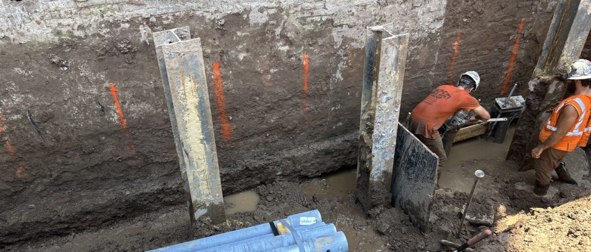
In dense urban infill projects, adjacent pile-driving operations frequently induce piledriving settlement in nearby unreinforced masonry structures. At 304 Johnson Ave. in Jersey City, heavy driving vibrations from adjacent H-pile installations triggered immediate foundation movement in an adjacent historic four-story brick structure situated just 3 feet from the property line.
While temporary rack bracing was installed to arrest lateral displacement of the adjacent wall, it does not transfer axial foundation loads to stable bearing strata.
A permanent underpinning design was required to arrest settlement without introducing additional vibration. Selecting the right method meant working through the soil conditions, structural loads, and site geometry together.
Why the Usual Options Were Off the Table
Impact-driven pile systems were immediately ruled out due to the high risk of further densification settlement or structural cracking within the unreinforced brick masonry. Conventional drilled shafts presented significant constructability challenges: low overhead clearance under the structural bracing prevented machine access, while high groundwater and cohesionless, collapsing soils turned test pits into unstable excavation hazards requiring continuous dewatering.
The site presented four compounding constraints:
- Limited access under bracing. Working under and around the temporary bracing left room for only short pile sections – 7-foot and 5-foot extensions instead of standard lengths.
- Difficult access. The bracing that was keeping the building standing was also an impediment to foundation stabilization.
- High water table. Any excavation to expose the footing filled fast.
- Collapsing soils. Pits wouldn’t stand open without constant dewatering, which meant the installation window at each pile location was narrow.
Helical underpinning piles provided the ideal engineering solution by addressing every site and soil constraint simultaneously: displacement-free and vibrationless installation, modular low-headroom advancement, immediate load transfer upon lock-off, and torque-correlated axial capacity verification without waiting for grout or concrete cure times.
The Design
The structural foundation design comprised 20 IDEAL 4.5-inch O.D. heavy-wall helical pipe piles engineered for a 50-ton ultimate axial capacity per location. Piles were advanced through weak overburden layers to a bearing stratum at a depth of 55 feet and integrated with heavy-duty underpinning bracket assemblies.
A few notes on the selections, for engineers evaluating similar conditions:
Round Pipe Shaft vs. Square Shaft Selection: In soft, saturated, or collapsing soil profiles where lateral overburden support is minimal, a 4.5-inch O.D. hollow structural section (HSS) pipe shaft provides significantly higher section modulus and bending stiffness compared with square shaft alternatives, mitigating structural buckling concerns over a 55-foot unbraced length.
Heavy-Duty Underpinning Bracket Assemblies: To support 50-ton axial design loads from multi-story masonry bearing walls, engineered heavy-duty bracket assemblies were required. These assemblies seat directly beneath the concrete footing, distributing concentrated load stresses and utilizing threaded jacking assemblies to lock off structural loads onto the pile shaft.
Modular Short Extensions in Low Headroom: Under 7-foot clearance constraints, 5-foot and 7-foot segmented extensions were used. Fully bolted, high-strength structural couplings ensured continuous torque transmission and full axial/torsional capacity transfer along the entire 55-foot pile length.
Installation Sequence
Installation was executed systematically to accommodate local soil instability and groundwater conditions:
- Excavate a pit at the pile location to expose the footing, with pumps running continuously to hold the water table below the working level.
- Advance the lead section and extensions with a hydraulic drive head on compact equipment, monitoring installation torque on every section.
- Continue to the design depth of 55 feet and the torque value correlated to the 50-ton design capacity – the torque log is the capacity record for each pile.
- Cut the shaft to grade and seat the heavy-duty bracket beneath the footing.
- Transfer load from the footing to the pile and lock off the bracket assembly.
- Backfill and move to the next location before the pit conditions deteriorate.
Step 3 represents the critical quality assurance control. By applying empirical torque correlation factors, real-time installation torque monitoring provided instantaneous verification of ultimate pile capacity at each location, ensuring immediate structural stability prior to pit backfilling.
The Result
The differential foundation settlement was completely arrested. The four-story masonry building was permanently underpinned to dense bearing strata at 55 feet, enabling the removal of temporary shoring and safe continuation of adjacent excavation and pile driving operations.
Project team: Installing contractor: Hale Built. Engineer: Hudson Engineering. GC: AM Development LLC.
Five Takeaways for Specifying Urban Underpinning
- Evaluate Helical Pile Type Based on Soil Parameters: Select pipe shafts with or without grout over square shafts and grouting when soil layers exhibit low shear strength or poor lateral confinement over deep unbraced lengths.
- Account for Low-Headroom Production Rates: Modular short extension sections solve spatial restrictions but increase mechanical coupling assembly cycles; schedules and pricing should reflect connection handling.
- Specify Underpinning Brackets for Structural Load Demands: Ensure brackets are explicitly specified for commercial design capacities and footing load distributions.
- Utilize Empirical Torque Correlation for Instant QA/QC: Torque-to-capacity verification allows immediate load lock-off and eliminates curing delays in unstable excavated pits.
- Require Zero-Vibration Systems Adjacent to Distressed Masonry: Helical installation generates zero dynamic vibration, safeguarding sensitive unreinforced historic structures during foundation remediation.
Planning an Underpinning Project?
Danbro Distributors supports engineers and contractors across our entire territory along the Eastern Seaboard, with IDEAL Helical Piles, heavy-duty underpinning brackets, and the technical support to put them to work under real-world constraints – from a Jersey City basement to a nuclear facility security wall. If headroom, access, vibration, or groundwater is driving your foundation repair decision, talk to our engineering team: /




No comments yet.